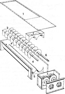
- Inlet opening matches bin or hopper discharge.
- Shroud cover prevents material flooding.
- Twin tapered, variable pitch Screw Conveyor permits even draw off of material.
- Twin tapered trough. Also available with drop bottom feature.
- Discharge opening.
- Solid shafting transmits rotary motion to driving gears.
- Driving gears synchronize the action of the screw conveyors.

Normally short in length, Screw Feeders are designed to regulate the volumetric rate of material flow from a hopper, bin or storage unit.
The inlet is usually flooded with material (100% load capacity) but by incorporating changes in the construction of the flighting (diameter, pitch, etc.) and the speed of the feeder screw, the material discharge can be governed to the desired rate. Feeders can be built with variable diameter or stepped pitch or both in units (com-posed of one, two or a multiple number of screws (i.e., Live Bottom Bin) depending on the application.
Screw Feeders are normally equipped with a shroud (curved) cover for a short distance beyond the inlet opening. This prevents flooding of the conveyor with material. When handling very freely flowing materials, extended shroud covers, tubular housing construction or short pitch flights are occasionally required for positive control.
Screw Feeders with uniform diameter and pitch normally convey the material from the rear of the inlet opening first. To draw off material evenly across the full length of the inlet, a tapered screw or stepped pitch conveyor screw is required. While Screw Feeders are available in many designs to fit your particular requirements, several commonly used types are described below.
Multiple Diameter Feeder
This is a combination feeder and conveyor and the physical dimensions are variable on each. The small diameter feed end will operate at a full cross sectional load. When the material reaches the larger section, the cross sectional load will be at a controlled safe maximum.
Short Pitch Feeder
This is also a combination feeder and conveyor. The short pitch end will handle full cross sectional loads. The material is then discharged into the standard section where the cross sectional load is reduced to the required maximum by the increase in screw pitch.
Variable Pitch Twin-Tapered Feeder
This feeder is popularly used to unload bins or hoppers at a controlled rate. The feed opening under the bin is designed large enough to prevent material bridging and accepts materials uniformly across the length and width of the opening. This eliminates dead areas in the bin and reduces the chance of material bridging or spoiling.
Live Bottom Feeder
Designed for use on straight sided bins, this feeder is composed of a number of feeder screws in tandem which serve as the bottom of the bin. Material is, therefore, drawn out equally from the full width. The Live Bottom Feeder is used to its best advantage on materials which tend to pack or bridge easily.
Screw Feeder Capacity
The capacity table on pg. 20 shows Screw Feeder Capacities in cubic feet per hour per RPM. This table relates to full pitch or standard conveyors only. Shorter pitch flighting will convey a capacity in direct ratio to the capacity of the full pitch. For instance, a 9″ conveyor with standard pitch (9″) flighting on a 2-1/2″ standard pipe, will convey 16.8 cu. ft./hr./RPM.
The same conveyor, but with 3″ pitch, will convey 1/3 this amount, or 5.6 cu. ft./hr./RPM. The capacity figure is theoretical. Actual capacity will often vary due to variation in head of material in the bin and variation in material characteristics.
Screw Feeder Speed
The speed of the feeder screw can be determined by dividing the desired capacity in cu. ft. / hr. by the figure found in Capacity Table. For maximum efficiency, feeder screw speeds should be slower than standard screw conveyor speeds and allowances must be made for slippage of the material in the screw.
Factors Affecting the Design Of A Screw Feeder
- The material class
- The material physical characteristics
- The capacity required
- Material factor “F”
- Weight of material resting on the Feeder Screw
- The dimensions of the feeder opening.

In designing a Screw Feeder, virtually every situation is unique in one respect or another. For this reason, we recommend that you consult Kase Engineering Department for proper recommendations concerning your particular needs.


