Proper selection of components is very important in the design of conveyor system. This section of the Engineering Catalogue explains the different designs of primary components, and their principle uses. Also, there is a list of special influencing factors for materials with special handling characteristics.
Conveyor Loading and Discharge
Conveyor loading should be regulated to prevent the components from exceeding their design limits.
Regulated Output Devices
When delivery to conveyor is from machinery with a regulated material output, the conveyor itself can be designed to handle the anticipated material volume.
Material is sometimes stored and released intermittently. In this situation, surge loads sometimes cause the conveyor to operate beyond its recommended capacity. Screw feeders are very effective in regulating these intermittent loads, and should be used if at all possible. Otherwise conveyors must be designed for the maximum momentary or surge loads.

Static Storage Loading
When loading from static storage or from manually regulated inlets, a load indicating ammeter can be attached to the meter control, as a simple and effective tool for accomplishing maximum design loading.
Multiple Inlet Loading
When more than one inlet is feeding the screw conveyor, care must be taken to insure the collective total of the inlets does not exceed the conveyors design limits.

Loading Through Automatic Controls
Automatic devices are available to modulate inlet or feed devices to work within design limits of the conveyor at all times.
Discharge Methods
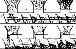
Below are drawings of standard discharge components in a variety of designs. These configurations are listed for individual applications where the standard discharge spouts are not necessarily appropriate. Cautions are inserted when necessary for particular discharge components.


Standard Discharge Spout
This component provides a means of directly coupling most interconnecting spouts, processing machinery, other conveyors or storage facilities. Available with hand, rack and pinion or air actuated cut off gates.
Flush End Discharge


Mechanically Operated Gates (Manual or Remote Controlled)
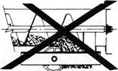
Caution: Not to be used on last discharge.


Plain Opening


Open Bottom Discharge


Trough End Discharge
Caution: To be used with conveyor loadings of 30% or under only.


Open End Discharge


Factors Influencing Materials of Construction or Special Mechanical Arrangement of Screw Conveyor Components
Corrosive Materials
Corrosive materials, or materials which have a tendency to become corrosive under certain conditions, may necessitate the use of corrosion-resistant alloys such as stainless steel.
Abrasive Materials
Abrasive materials which may cause excessive wear of components should be conveyed at a nominal depth in the conveyor. It is often advisable to also specify Kase’s Abrasion-Resistant Screw Conveyors or conveyors with flights formed of AR steel plate.
Kase’s Abrasion-Resistant Screw Conveyors, which have a Rockwell C hardness of 68-70, are covered in the Component Section. A table listing the standard width of application of hard surfacing is included.
Contaminable Materials
Materials whose usefulness or value may be altered by contamination may require the use of non-lubricated bearings, as well as a tightly sealed system.
Hygroscopic Materials
Materials that readily absorb moisture require a tightly sealed conveyor. It may be necessary also to jacket the conveyor trough or housing with a circulating medium to maintain an elevated temperature. Purging the system with dry gas or air may be necessary.
Interlocking Materials
Materials which tend to mat or interlock are sometimes effectively conveyed by using special devices to load the conveyor.
Fluidizing Materials
Some materials tend to assume hydraulic properties when aerated or mechanically agitated. Such materials may “flow” in the conveyor much the same as a liquid. These materials should be referred to Kase’s engineering department for recommendations.
Explosive Materials
Dangerous explosive materials can be handled by sealing the system and/or the use of non-sparking components. It is also possible to utilize exhaust systems for hazardous dust removal.
Materials Which Tend to Pack
Materials that tend to pack under pressure can frequently be handled by using aerating devices (for fine materials) or special feeding devices (for large or fibrous particles).
Viscous or Sticky Materials
Viscous or sticky materials are transported most effectively by ribbon conveyors.
Degradable Materials
Materials with particles that are easily broken may be effectively handled by selection of a larger, slower conveyor.
Elevated Temperatures
Materials handled at elevated temperatures may require components manufactured of high-temperature alloys. If it is feasible to cool the material in transit, a jacketed trough used as a cooling device may also be employed.
Toxic Materials
Materials which emit harmful vapors or dusts require tightly sealed systems. Exhaust devices may also be used to remove the vapors or dusts from the conveyor housing.
Description of Components
Conveyor Screws
The recommended screws listed in the Component Series Table are standard Kase helicoid and sectional screw conveyors. The use of helicoid or sectional conveyors is largely a matter of individual preference.
It is advisable to use, whenever possible, standard conveyors in standard lengths. When a special short length must be used to make up the total conveyor length, it is preferably located at the discharge end.

Screw conveyors are structurally reinforced at the ends by the use of end lugs which are welded to the non-carrying side of the flights so that material flow will not be obstructed.
Screw conveyors which move material in a single direction should not be turned end-for-end unless the direction of screw rotation is reversed. Likewise, the direction of rotation should not be reversed unless the conveyor is turned end-for-end. Requirements for reversible conveyors should be referred to Kase’s Engineering Department. Flighting should be omitted at the final discharge, so that material will not carry past the discharge point.
To assure proper material flow past hanger bearing points, flight ends should be positioned to each other at 180 degrees.
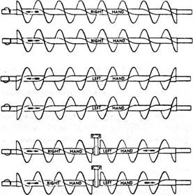
The “hand” of a conveyor, in conjunction with the direction the conveyor is rotated, determines the direction of material flow. The diagram below illustrates flow direction for “right-hand” and “left-hand” conveyors when rotated clockwise or counterclockwise.
A right-hand screw conveyor pulls the material toward the end which is being rotated clockwise. The direction of flow is reversed when the direction of rotation is reversed.
A left-hand conveyor pushes the material away from the end which is being rotated clockwise. Again, the direction of material flow is reversed when the direction of rotation is reversed.
To determine the hand of a conveyor, observe the slope of the near side of the flighting. If the slope is downward to the right, the conveyor is right-hand. If the slope is downward to the left, the conveyor is left-hand. Right-hand conveyor is furnished unless otherwise specified.
Troughs and Tubular Housings
Kase troughs and tubular housings are available in standard lengths. Special lengths are available when required. All conveyor troughs or tubular housings should be supported by flange feet or saddles at standard intervals. Extreme end flanges should be supported with feet so that the conveyor ends may be removed without disturbing trough or housing alignment.
Inlets and Discharges
The proper methods of conveyor loading and discharge were covered previously in this section.
Shafts
The primary consideration in determining the type and size of coupling and drive shafts is whether the shafts selected are adequate to transmit the horsepower required, including any overload. Normally, cold-rolled shafts are adequate. However, high-tensile shafts may be required due to torque limitations. Also, stainless steel shafts may be necessary when corrosive or contaminable materials are to be handled. Conveyors equipped with non-lubricated iron hanger bearings require hardened coupling shafts, and hard-surfaced hanger bearings require hard-surfaced shafts. Specific shaft size determination is covered in the Torque Capacities Section.
Shaft Seals
Several conveyor end seal types are available to prevent contamination of the conveyed material or to prevent the escaped of material from the system.
Bearings
Hanger Bearings – The purpose of hanger bearings is to provide intermediate support when multiple screw sections are used. Hanger bearings are designed primarily for radial loads. Adequate clearance should be allowed between the bearings and the conveyor pipe ends to prevent damage by the thrust load which is transmitted through the conveyor pipe.
The hanger bearing recommendations listed in the Component Series Table are generally adequate for the material to be handled. Often, however, unusual characteristics of the material or the conditions under which the conveyor must operate make it desirable to use special bearing materials. A list of available special bearing materials is provided in this section. For specific recommendations regarding the use of special bearing materials, consult Kase’s Engineering Department.
End Bearings – Several end bearing types are available, and their selection depends on two basic factors: Radial load and thrust load. The relative values of these loads determines end bearing types.
Radial load is negligible at the conveyor tail shaft. However, drive ends (unless integrated with the conveyor end plate) are subject to radial loading due to overhung drive loads, such as chain sprockets or shaft-mounted speed reducers.
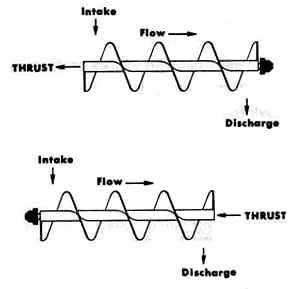
Thrust is the reaction, through the conveyor screw or screws, resulting from movement of the material. Therefore, the end bearing must prevent axial movement of the screw which would allow contact with hanger bearings or ends. Thrust bearings should be located at the discharge end of the conveyor. This places the conveyor in tension, preventing deflection in the screws when the system is heavily loaded. The following diagrams illustrate discharge and inlet end positions of the thrust bearing.

Component Series
The recommended Component Series for the material to be conveyed may be found in the Materials Table at the beginning of the Engineering Section. The alphabetical code relates to the general component series, and the numerical code refers to bearings and coupling shafts. The Component Series Table follows on the next page. Bearing and coupling shaft recommendations are listed in the table below. The Component Series Table lists the screw conveyor numbers for both helicoid and sectional screws and gives the trough and cover thicknesses. The Bearing and Coupling Shaft Table lists the recommended materials of construction.
| Series | Coupling Shaft | Bearing Material |
|---|---|---|
| 1 | Standard or High Torque | Babbitt Wood Bronze |
| 2 | Standard or High Torque | Babbitt Wood Bronze Ball |
| 3 | Standard or High Torque | Babbitt |
| 4 | Hardened or Hard Surfaced | Hard Iron Hard Surfaced |


